Difference between revisions of "Guider"
| Line 1: | Line 1: | ||
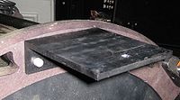
An SBIG SG-4 autoguider was added to the Moore Observatory CDK20 in October 2009. It is mounted on the bracket originally designed to hold a Nikon DSLR and wide-field lens under the telescope. However, in that position, the guider will not clear the mount as the telescope rotates in declination. The bracket was moved to the "top" of the telescope and secured to the central truss ring by two 1/4-20 stainless steel allen-head cap screws. The Nikon attachment plate has a rib on the underside that reduces flexure. | An SBIG SG-4 autoguider was added to the Moore Observatory CDK20 in October 2009. It is mounted on the bracket originally designed to hold a Nikon DSLR and wide-field lens under the telescope. However, in that position, the guider will not clear the mount as the telescope rotates in declination. The bracket was moved to the "top" of the telescope and secured to the central truss ring by two 1/4-20 stainless steel allen-head cap screws. The Nikon attachment plate has a rib on the underside that reduces flexure. | ||
[[File:Nikon_bracket_sm.jpg|200px|thumb|left| | [[File:Nikon_bracket_sm.jpg|200px|thumb|left|Nikon bracket]] | ||
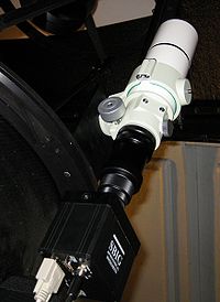
The guider is presently used with a Takahashi 60 mm diameter apochromatic refractor with a focal length of 355 mm. The assembly is held by a Takahashi tube mount, and bolted to the Nikon plate with a single 1/4-20 screw. The strength of this attachment derives from the large contact area. | The guider is presently used with a Takahashi 60 mm diameter apochromatic refractor with a focal length of 355 mm. The assembly is held by a Takahashi tube mount, and bolted to the Nikon plate with a single 1/4-20 screw. The strength of this attachment derives from the large contact area. | ||
[[File:Sg4_tak60.jpg|200px|thumb|left| | [[File:Sg4_tak60.jpg|200px|thumb|left|SG-4 autoguider]] | ||
The SG-4 requires a serial connection to the control computer and 12V DC power. On the Moore telescope, the 12V is supplied by a powerbrick that is carried on the OTA and connected to the web powerswitch "Camera" control. The serial line is connected through a DB9 and 6-foot serial extension cable to a Cat5 cable with DB9 adapters that goes to pegasus, the Sirius dome computer. | The SG-4 requires a serial connection to the control computer and 12V DC power. On the Moore telescope, the 12V is supplied by a powerbrick that is carried on the OTA and connected to the web powerswitch "Camera" control. The serial line is connected through a DB9 and 6-foot serial extension cable to a Cat5 cable with DB9 adapters that goes to pegasus, the Sirius dome computer. | ||
| Line 11: | Line 11: | ||
Pegasus runs with a Siig PCI serial card that adds two ports to the machine. These ports appear as ttyS4 and ttyS5. (To see the port assignments, use dmseg | less and search for tty.) On the Moore telescope the ttyS5 port is used for the guider connection. This is set in the prefs.guider file. | Pegasus runs with a Siig PCI serial card that adds two ports to the machine. These ports appear as ttyS4 and ttyS5. (To see the port assignments, use dmseg | less and search for tty.) On the Moore telescope the ttyS5 port is used for the guider connection. This is set in the prefs.guider file. | ||
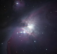
[[File:Orion_100s_log.jpg|200px|thumb|right| | [[File:Orion_100s_log.jpg|200px|thumb|right|M42 with the CDK20]] | ||
The guider in this location tracks with an accuracy of at least 1.5 arcseconds full width at half maximum in 60 second exposures. One of the first images taken with this system was of M42 on the night of October 28-29, 2009. | The guider in this location tracks with an accuracy of at least 1.5 arcseconds full width at half maximum in 60 second exposures. One of the first images taken with this system was of M42 on the night of October 28-29, 2009. | ||
Revision as of 22:37, 30 October 2009
An SBIG SG-4 autoguider was added to the Moore Observatory CDK20 in October 2009. It is mounted on the bracket originally designed to hold a Nikon DSLR and wide-field lens under the telescope. However, in that position, the guider will not clear the mount as the telescope rotates in declination. The bracket was moved to the "top" of the telescope and secured to the central truss ring by two 1/4-20 stainless steel allen-head cap screws. The Nikon attachment plate has a rib on the underside that reduces flexure.
The guider is presently used with a Takahashi 60 mm diameter apochromatic refractor with a focal length of 355 mm. The assembly is held by a Takahashi tube mount, and bolted to the Nikon plate with a single 1/4-20 screw. The strength of this attachment derives from the large contact area.
The SG-4 requires a serial connection to the control computer and 12V DC power. On the Moore telescope, the 12V is supplied by a powerbrick that is carried on the OTA and connected to the web powerswitch "Camera" control. The serial line is connected through a DB9 and 6-foot serial extension cable to a Cat5 cable with DB9 adapters that goes to pegasus, the Sirius dome computer.
Pegasus runs with a Siig PCI serial card that adds two ports to the machine. These ports appear as ttyS4 and ttyS5. (To see the port assignments, use dmseg | less and search for tty.) On the Moore telescope the ttyS5 port is used for the guider connection. This is set in the prefs.guider file.
The guider in this location tracks with an accuracy of at least 1.5 arcseconds full width at half maximum in 60 second exposures. One of the first images taken with this system was of M42 on the night of October 28-29, 2009.
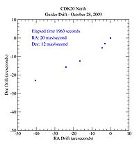
There is flexure in the guider mount that causes a drift of the axis of the SG-4 with respect to the CDK20 with changing orientation of the telescope. When the images of M42 were recorded, this flexure progressed linearly in both declination and right ascension at a rate of the order of 15 milliarcseconds per second. The OTA was on the west side of the pier pointing southeast, with Orion at azimuth approximately 120 degrees. In this orientation the "x" and "y" axes of the guider were rotated to the vertical and the changing load apparently was sufficient to twist the guider axis. A plot of the accumulated pointing error is shown in the figure.


