Difference between revisions of "Dome Control"
| Line 38: | Line 38: | ||
The device provides a robust configurable interface that enables simple web-based control of the dome shutters and rotation. Since it runs its own internal server. interfacing with it is simple through TCP/IP over port 80. | The device provides a robust configurable interface that enables simple web-based control of the dome shutters and rotation. Since it runs its own internal server. interfacing with it is simple through TCP/IP over port 80. | ||
The user | |||
<center>[[File:Dome relay control.jpg| 600 pix]]</center> | |||
Each labelled relay controls a single normally open line, and connects it to the dome 12 VDC system to switch on that function. The lines are color coded, and connected by a 9-wire cable that is terminated with a Phoenix Contact connector close to the DIN controller: | |||
*Rotate CW (decrease azimuth) - yellow to relay 1 | |||
*Rotate CCD (increase azimuth) - brown to relay 2 | |||
*Open Upper - orange to relay 7 | |||
*Close Upper - green to relay 8 | |||
*Open lower - blue to relay 5 | |||
*Close lower - violet to relay 6 | |||
This choice of relay order was made to leave a gap on the user interface between shutter and dome rotation. It also avoids relay 3 which, on the module in the CDK20N dome, may have a high resistance contact. | |||
Revision as of 05:50, 23 October 2011
The domes at Moore and Mt. Kent observatories have their own control systems designed to interface with the electromechanical hardware supplied by the dome manufacturer. The esstential cdesign elements shared by all domes are
- Rotation encoder
- Rotation motor controller
- Shutter status monitor
- Shutter motor controller
- Software connected to the telescope control system
This page is a description of the dome control hardware and software highlighting similarities and differences between the systems for the two Sirius domes housing the CDK20's, the Ash dome for the RC24, and a refurbished dome for the CDK700.
Sirius Dome for CDK20N
The original Sirius electronics control dome rotation and the opening and closure of the upper and lower shutters. The control board is proprietary, but its operation is determined by wiring to screw terminals that we have modified to connect to external systems.
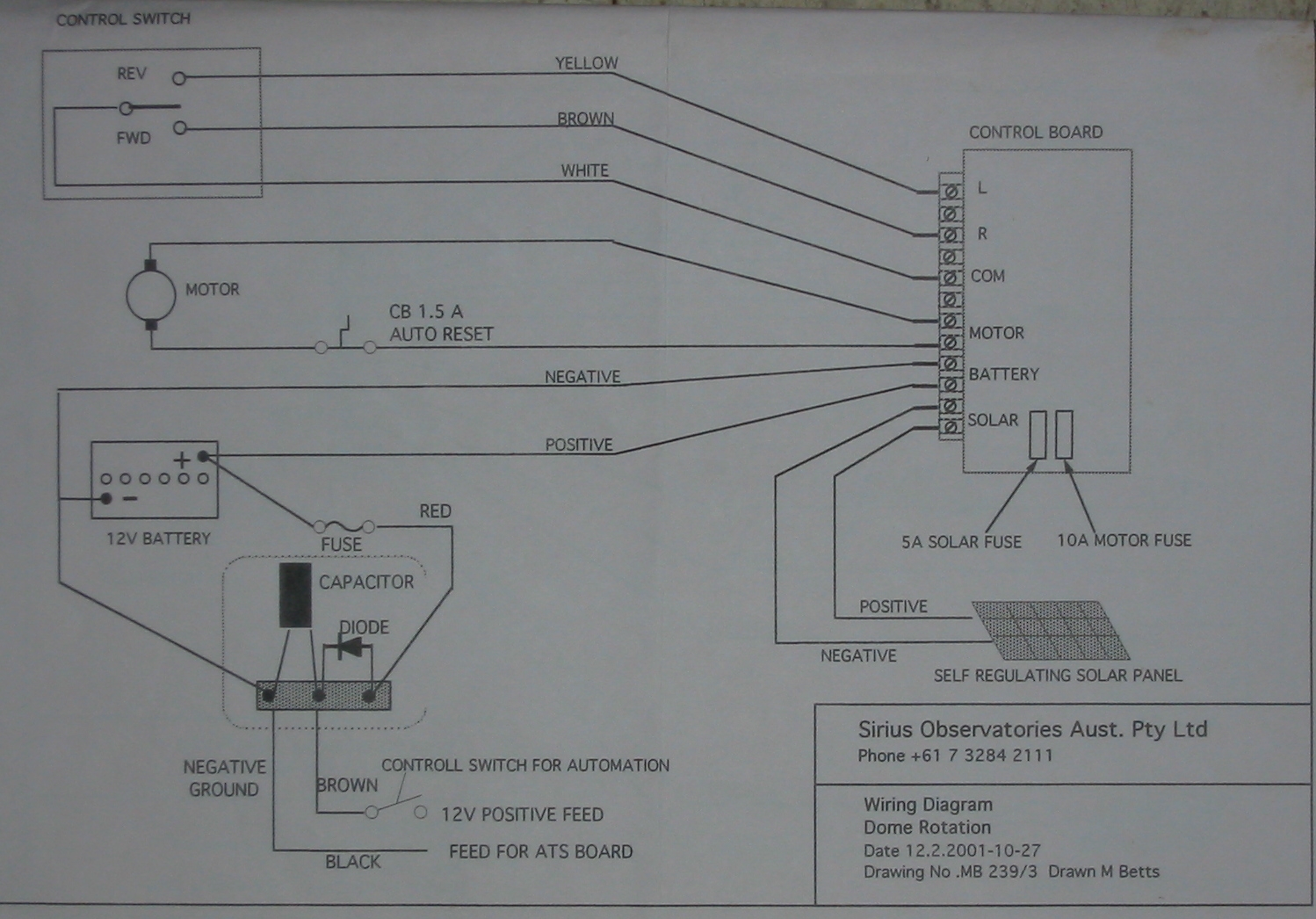
This schematic shows a how a switch will apply 12 VDC power to one of two lines that select the direction of rotation, or similarly opening or closing the two shutters. In computer controlled operation there is a relay system in parallel with the manual switch, such as shown here:
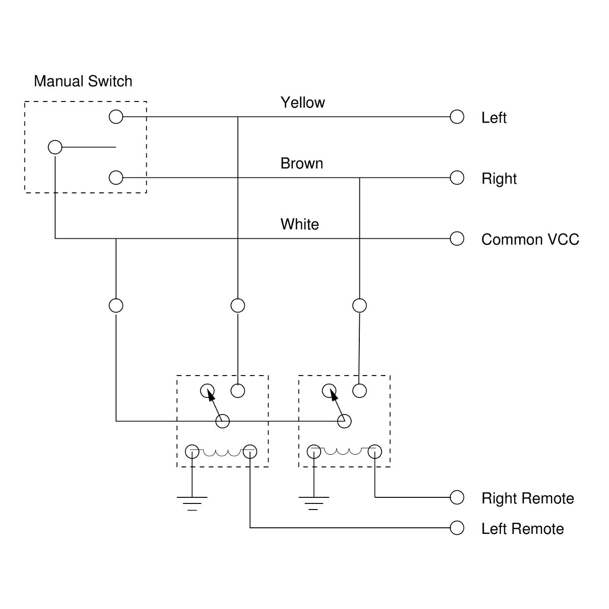
with the power for the relays provided by the "COM" 12 VDC power of the dome electronics. Note that "COM" is not ground, but the common 12VDC form the battery power of the system. Fuses and circuit breakers protect the motors from overload, and the control board is designed so that most operations are safe. In this respect, there are limit switches on the shutter motion that turn off power to the motors with the shutters are fully open or closed. There is no hard wired logic to insure that thelower shutter is closed before the upper shutter drops down over it, however.
At CDK20N we have a relay box mounted on the dome wall containing 6 socketed industrial relays with 12 VDC coils. The relays are wired such that the application of the "COM" voltage to a control line causes the relay to close with the same effect as the corresponding switch.
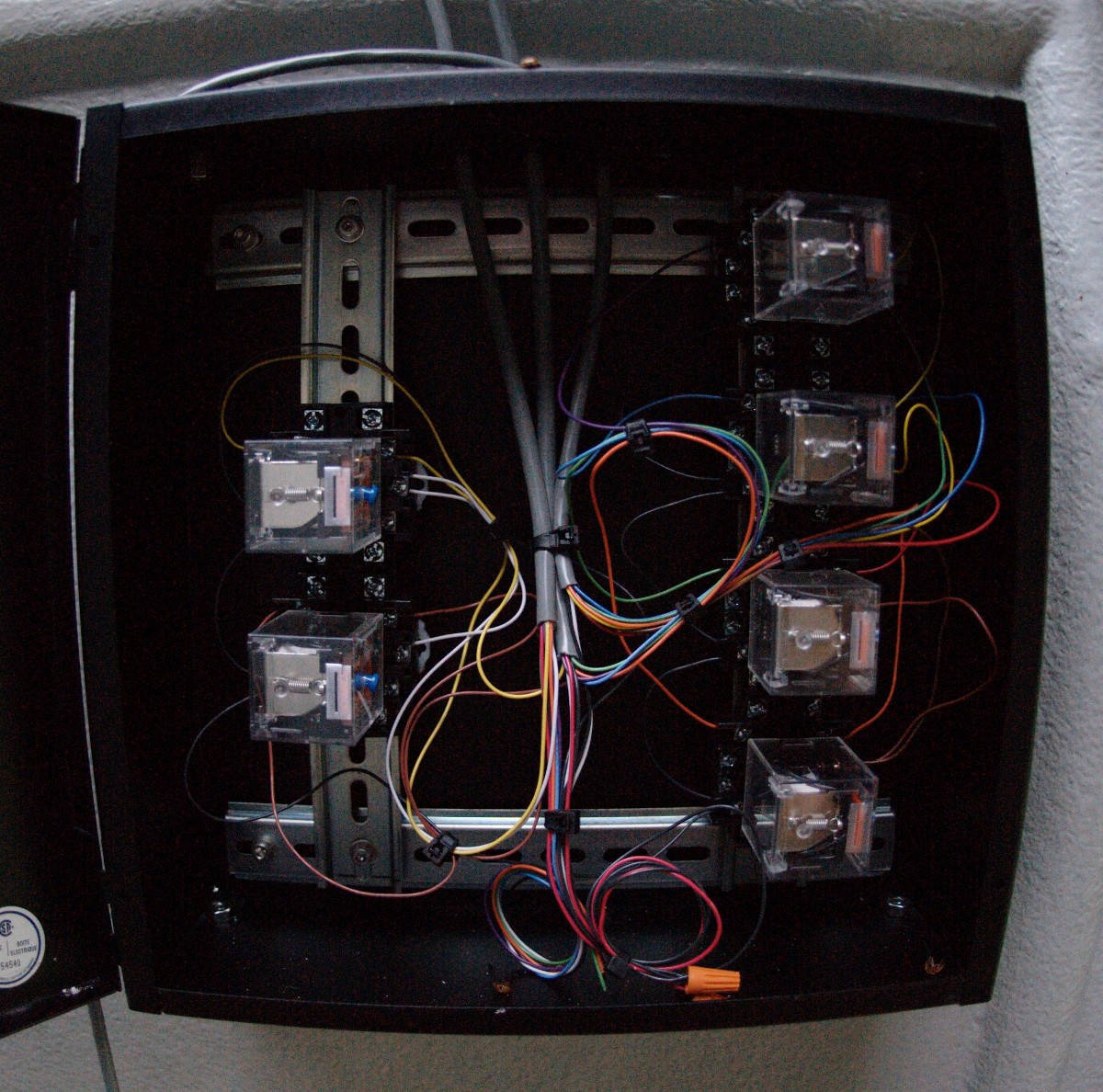
There is a dropline from the dome electronics to the relay box to allow the connection of the static relay system to the rotating dome. The line falls at the perimeter of the dome. When the line is in use, software prohibits rotating the dome through azimuth 0 (shutter opening to the north) to lessen the chance of the cable snagging. The dropline is connected through an 8-pin Phoenix Contact connector that will pull apart if the cable is caught.
The relay box may be controlled by logic level electronics or by a web switch. In the first generation of this system a National Instruments PCI-6518 digital logic controller with open collector connections. In the fall of 2011 we replaced this with a Digital-Loggers Web Din Relay shown here:
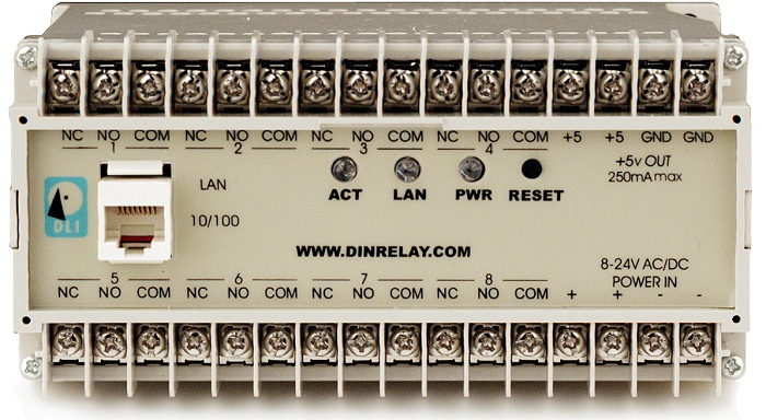
The device provides a robust configurable interface that enables simple web-based control of the dome shutters and rotation. Since it runs its own internal server. interfacing with it is simple through TCP/IP over port 80.
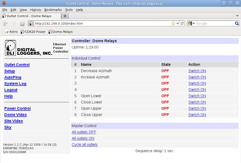
Each labelled relay controls a single normally open line, and connects it to the dome 12 VDC system to switch on that function. The lines are color coded, and connected by a 9-wire cable that is terminated with a Phoenix Contact connector close to the DIN controller:
- Rotate CW (decrease azimuth) - yellow to relay 1
- Rotate CCD (increase azimuth) - brown to relay 2
- Open Upper - orange to relay 7
- Close Upper - green to relay 8
- Open lower - blue to relay 5
- Close lower - violet to relay 6
This choice of relay order was made to leave a gap on the user interface between shutter and dome rotation. It also avoids relay 3 which, on the module in the CDK20N dome, may have a high resistance contact.