RC24 Focuser
The RC Optical Systems 24-inch Ritchie-Chretien telescope at Moore Observatory (MORC24) is focused with a motor-driven secondary. The original electronics was a TCC instrument control package that connected to the motor on the secondary, controlled the fans behind the primary, and read the thermistors on both primary and secondary mirror backs. The unit malfunctioned in August 2014 when it stopped reading the motor encoder and it was removed from service. This page documents our replacement.
We also note that a custom replacement part may be available from RA Limited LLC. We chose to develop a control that used hardware similar to that on our other telescopes.
Original Parts and Wiring
The telescope was wired through the primary mirror cell using an 18-pin Amphenol connector on the back plate. The pin assignments on this connector were not documented by RC Optical, but they iare known to include these functional groups:
- Secondary mirror motor power (12 V)
- Secondary mirror encoder power (5 V)
- Secondary mirror encoder phase A
- Secondary mirror encoder phase B
- Secondary mirror temperature thermistor
- Air temperature thermistor
- Primary mirror thermistor
- Primary mirror fan power
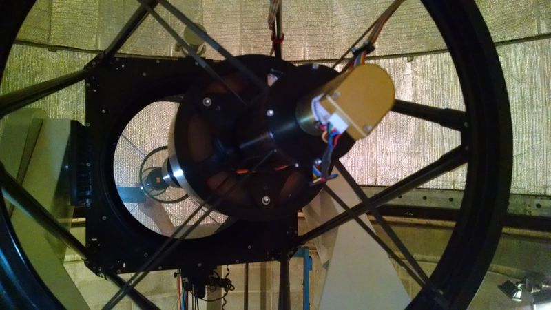
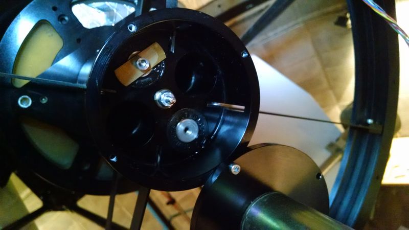
This connector and the fans are only accessible for rewiring by removing the primary mirror cell, which in the first phase of repair we did not do. The original wiring to the fan motors is clipped into the motor supports and is accessible from the outside since the fans are not covered. There was a ribbon cable leading from behind the primary up one truss to the top ring where it crossed to the secondary. At the point of crossing a thermistor was exposed to measure air temperature. The ribbon cable was clamped so as to be partly hidden behind a spider vane, as shown in the photo above. Behind the secondary mirror this cable terminated in connectors to the focus drive motor and what appears to be a thermistor taped to the back of the secondary. The ribbon cable was held flat by two clamps.
The ribbon cable clamps were held by 6-32 screws passing through holes in the inclined spider vane. The innermost of these holes was incorrectly located such that the cable clamp was in the optical path.
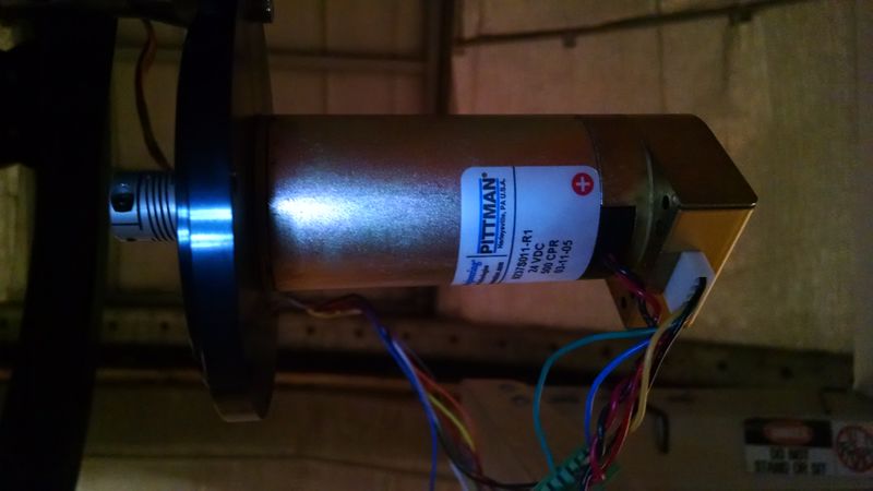
The only specific part that can be fully identified is the drive motor:
- Pittman 9237S011 24 VDC brushed DC motor
The secondary mirror motor power was divided over 3 lines for DC + and 3 more for ground in the original ribbon cable. The replacement cable uses 22 gauge wiring adequate to carry each power lead in one wire.
The polarity determines the direction the motor rotates so that is ambiguous and effectively set in software. The encoder connection allows 5 lines with these assignments and color codes from the Pittman DC motor documentation:
- Black - Ground (pin 1)
- Green - Index (pin 2, clipped at motor)
- Yellow - Channel A (pin 3)
- Red - Vcc for encoder (pin 4)
- Blue - Channel B (pin 5)
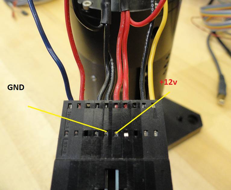
The wire colors are visible in the photo of the motor. Pins on the motor encoder plug are numbered from the left looking on the back of the motor or encoder with the connector down. In the original ribbon cable the encoder wires are on the outside of the ribbon with the motor power wires on the inside to minimize crosstalk between motor powe transients and the digital encoder signals. A photo of the original ribbon connector with wiring patter from the Swarthmore RC24 is shown below.
In the original wiring the inner wires were used for power and the outer wires for the encoder signal.The outer red and black wires are +5V encoder power and ground. The encoder phases A and B signals are the yellow and blue lines. The encoder green wire is not connected. In the replacement wiring a Phoenix connector also carries a thermal sensor wiring pair.
Focus Mechanical System
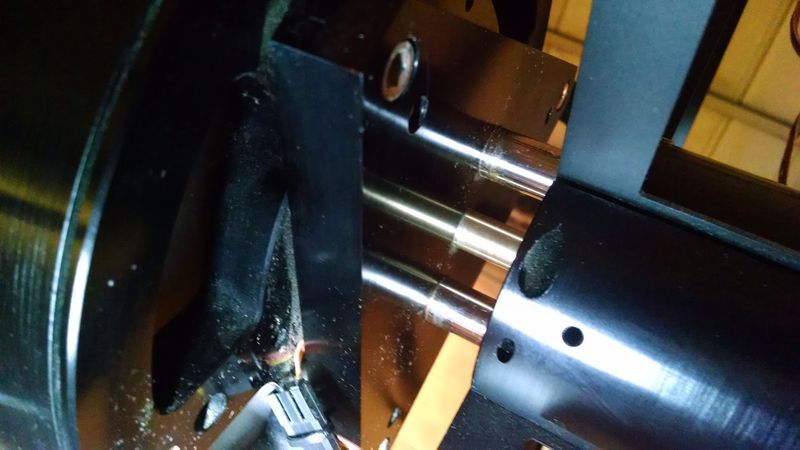
The secondary mirror cell is supported by two shafts that appear to be hardened stainless steel. The shafts ride smoothly in bearings that allow the mirror to move 25 mm along the optical axis. The mirror is held in position by an actuator that threads into another supporting shaft such that a rotation of the actuator pushes or pulls the mirror cell.
The upper end of the rotating actuator shaft is 4 mm in diameter. It is coupled with the 4 mm drive shaft of the Pittman motor by a flexible coupling that allows for minor shaft misalignment with no backlash. Thus one rotation of the motor shaft advances the secondary mirror 1/20 of an inch. A counterclockwise sense looking toward the primary from the motor backs the actuator screw out of the translator shaft and forces the secondary toward the primary. Similarly, a clockwise rotation pulls the secondary away from the primary toward the motor by 1/20 inch or 1270 microns per turn.
Motion toward the primary is stopped by a brass tab attached with a 10-32 screw to the back of one of the two support rods. The tab meets the inside of the coupling housing and blocks forward movement before the mirror actuator unscrews from the drive rod. In the opposite direction, the motion of the secondary away from the primary is stopped when a rotating arm on the motor shaft hits the edge of the cap screw holding the brass tab.
The rotation of the drive screw is very smooth and requires little torque, except for a few sticky places. In the course of the refitting in 2014 we lightly lubricated the shaft and screw with comparator oil when the motor was removed to assess whether there was significant binding. The photo above shows the motor in its flange temporarily held out of the way with one of the flange mounting screws. Access to the coupling set screw is through the slots for the spider vanes.
New Electronics
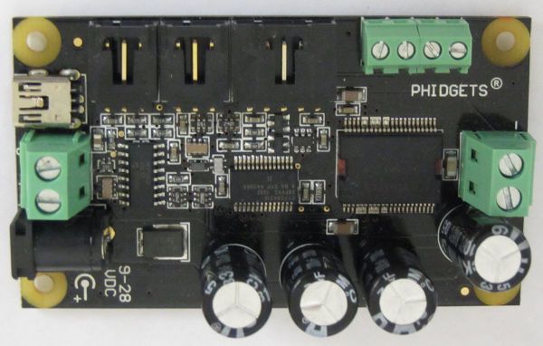
The TCC unit was removed and replaced with a Phidgets 1065 USB Motor Control Module. This is the same module used in the CDK20 focuser controls.
The controller receives logic power from the USB bus and motor power from a separate motor power supply (up to 28 VDC). It accepts standard TTL A and B encoder phases, and it supplies 5 V encoder interface power. The connectors also accept analog input from two temperature sensors and digital input from two lines. Phidgets open source libraries may be used to develop programs in C and Python on Linux, Windows, and Mac OS platforms.
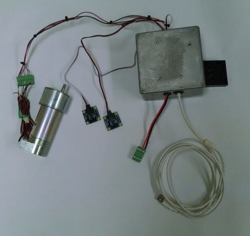
The new controller is enclosed in a cast aluminum box attached to the original TCC bracket on the primary mirror cell. DC motor supply power is routed to a 24 VDC linear supply in the equipment rack. The USB connection connection goes through a powered extender to the telescope control computer. Two thermistor sensors are connected to monitor the temperatures on a truss rod and behind the primary cell.
The SPDT spring loaded switch on the enclosure connects ground to the two digital inputs. The inputs may be read in software to enable an observer at the telescope to make focus adjustments. The original TCC hand control paddle is no longer used because the RC24 telescope is ordinarily operated by a remote observer.
Software
Focusers on the RC24 and CDK20 telescopes are controlled by Pyfocus, a suite of Python programs that provide for command line and scripted operation, and monitoring focus setting and temperature. The open source and MIT licensed code is available from our servers here
The available commands for focus and temperature are
- focus_change_microns moves the secondary a commanded distance in microns
- focus_change_pixels changes the PSF FWHM a commanded number of pixels in the CCD image
- focus_get reads the last encoder count
- focus_reset resets the encoder reference count
- focus_show_all displays the encoder count, mirror position, and PSF FWHM
- temperature_read inquires, displays, and saves the temperature readings
