CDK20 Focuser
The CDK20 telescopes have Hedrick focusers that provide stable positioning of the camera and filter wheel assembly at the fixed focal plane of the telescope. The same type of focuser is used on the CDK125 telescope.
Mechanical System
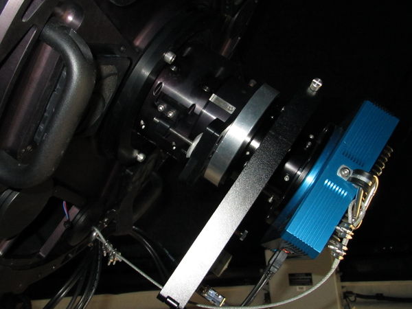
The focuser on the CDK20N is shown below.
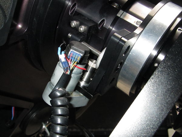
The camera is attached to a flanged tube centered on the optical axis of the telescope. The tube is constrained by roller bearings so that it cannot move laterally but can freely move in and out over a range of more than 30 mm with respect to the focal plane. One end of the leadscrew has a retainer that allows the leadscrew to rotate in a bearing attached to the focus tube. The leadscrew threads into a block that is attached to the focus tube housing. When the leadscrew rotates clockwise seen from the camera, it is pulled into the threaded block and the camera is translated toward the primary mirror. One turn of the screw advances the camera 1/32 inch or 0.794 mm.
A focus motor drives a bevel gear that engages a matching gear attached to the leadscrew that moves the camera. Since the screw has 32 threads per inch, one turn advances the camera focal plane 794 microns. The bevel gear and screw are clearly seen in this picture of the CDK20N Apogee camera.
When the motor assembly is removed the bevel gear may be rotated by hand to focus the telescope manually. At f/6.8 for the CDK20's, one turn of the focuser bevel gear will change the diameter of a stellar image by 794/6.8 = 117 microns. Since the Apogee cameras have 9 micron pixels, the change in the apparent image size is approximately 13 pixels per turn. In typical seeing we can optimize best focus for point spread functions of the order of 1 to 2 arcseconds, or 2 to 3 pixels, with final adjustments of the order of 1/8 of a turn.
Motor and Encoder
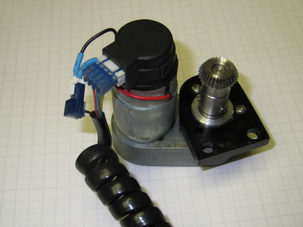
The CDK20 focuser motor is a DC servo with an integral optical encoder. A stock Celestron CPC telescope RA or declination motor has been augmented with a machined plate to attach it to the focuser. The bevel gear, approximately 1/2 the diameter of the matching gear on the focuser, engages the focuser gear. There is a shaft extension that positions the motor gear and matches the motor's 6 mm shaft to the gear's 0.250-inch bore. On the CDK20's the spacing may require shims.
The motor that was provided with our telescopes is similar to one also provided with the Hedrick focuser on our CDK125. Apart of the wiring differences which are undoubtedly the result of product development, the motor on the CDK125 has a lower gear ratio and therefore lower torque than the one on the CDK20. Consequently, they are not interchangable because our CDK20's will stall with the low torque motor. It appears that the high torque version is no longer offered as a standard Celestron replacement part.
The motor assembly is shown below.
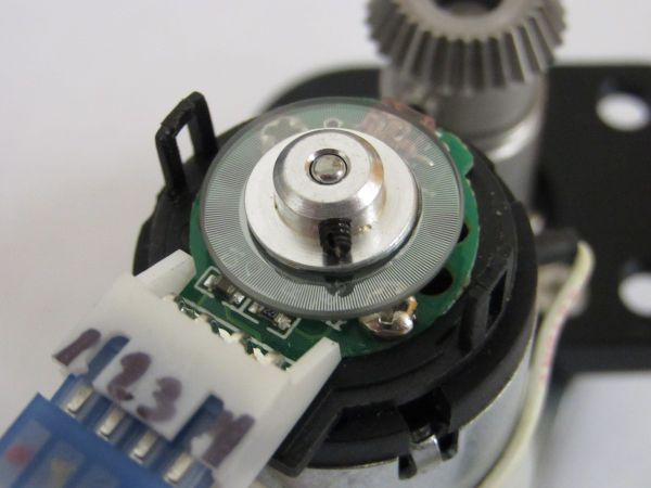
The motor gearing and encoder counts/turn are undocumented. However, the encoder is an E4 Optical Kit Encoder from US Digital. (The part is currently obsolete and replaced by a similar E4P.) The encoder connector is numbered by the manufacturer starting at pin 1 on the left, facing the connector with the optical disk up. A close-up view is shown below.
Based on the E4P datasheet, the pins are
- 1 +5 VDC
- 2 Encoder phase A
- 3 Ground
- 4 Encoder phase B
The encoder incorporated in the motor is an Agilent AEDR-8300 series reflective surface mount optical integrated circuit. The external connector pinout from the datasheet agrees with tracing the functional connections on the original focuser electronics.
There are three cautionary notes about wiring. First, the cable connector supplied by Celestron and by Planewave is not a perfect match to the encoder. While it has the correct pin spacing, it is slightly oversized and does not lock into the encoder, so that it can work loose during use. Second, the numbering faintly visible on the blue connector shown in the figure is in reverse order from the sequence in the E4P specification. Third, the wiring from the connector to the RJ45 used by Celestron and Planewave is different in the three examples of the focuser we have.
The encoder has a 4-position connector for power and TTL output, and the 12 VDC motor has two leads. In Planewave's wiring the six wires are terminated in an RJ45 (8P6C) connector. The wiring of this connector on the CDK20 telescopes is different from the wiring on the CDK125 (and presumably also from the wiring on the CDK20's currently produced by Planewave). The focuser motor shown is the one from CDK20N. The red and black wires supplying motor power are connected to the RJ45 cable through a 2P connector, and the 4P connector is for the encoder.
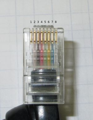
This picture of the connector on the CDK20N telescope shows pins numbered 1 to 8 from left to right with the clip down in the standard convention for numbering 8P8C (RJ45) connectors. The encoder connector pins are numbered 1 to 4 from left to right looking down on the encoder end of the motor with the encoder up. On both CDK20N and CDK20S, RJ45 pins 1 and 8 are not connected:
CDK20N
- RJ45 pin 1 NC
- RJ45 pin 2 white motor black motor-
- RJ45 pin 3 black motor red motor+
- RJ45 pin 4 orange encoder pin 4 +5V
- RJ45 pin 5 green encoder pin 2 ground
- RJ45 pin 6 yellow encoder pin 1 B
- RJ45 pin 7 blue encoder pin 3 A
- RJ45 pin 8 NC
CDK20S
- RJ45 pin 1 NC
- RJ45 pin 2 white motor red motor+
- RJ45 pin 3 black motor black motor-
- RJ45 pin 4 red encoder pin 4 +5V
- RJ45 pin 5 green encoder pin 2 ground
- RJ45 pin 6 yellow encoder pin 1 B
- RJ45 pin 7 blue encoder pin 3 A
- RJ45 pin 8 NC
CDK125
- RJ45 pin 1 gray encoder pin 2 ground
- RJ45 pin 2 orange encoder pin 4 +5V
- RJ45 pin 3 black motor white motor-
- RJ45 pin 4 red motor red/white motor+
- RJ45 pin 5 green encoder pin 1 B
- RJ45 pin 6 yellow encoder pin 3 A
- RJ45 pin 7 blue NC
- RJ45 pin 8 violet NC
To avoid any possible confusion and to enable adapting the motors to new controllers, we removed these RJ45 connectors and substituted Phoenix Contact 8-position pluggable terminal blocks with the following sequential pin assignments:
- Phoenix pin 1 encoder pin 1 +5VDC
- Phoenix pin 2 encoder pin 2 A
- Phoenix pin 3 encoder pin 3 ground
- Phoenix pin 4 encoder pin 4 B
- Phoenix pin 5 NC
- Phoenix pin 6 NC
- Phoenix pin 7 motor+
- Phoenix pin 8 motor-
Phidgets 1065 Servo Control
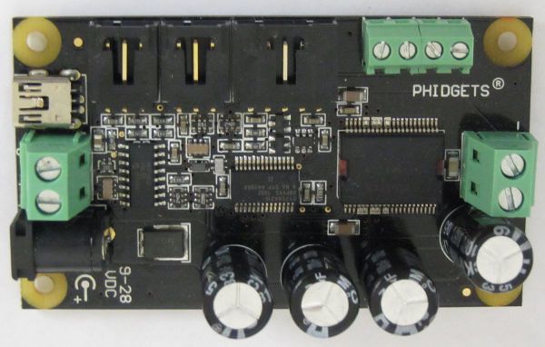
Phidgets makes products for USB sensing and control that are useful for instrumentation and telescope automation. These include the RFID tag reader we use for dome encoding, a GPS unit that can provide accurate time and position, environmental sensors, and several small DC motors with encoders similar to the one on the focuser. Control of a single motor with an encoder is provided by their Part Number 1065 Servo Controller shown below.
The board requires 9 to 28 VDC power and returns a the PWM control power to the small motor. It keeps a total full count (not the more precise quarter wave count) of each encoder transition. An open source library accompanied by C, Java, and Python examples allows straightforward interfacing of their devices to telescope control programs.
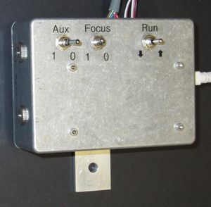
We enclose the servo control card in a separate aluminum box near the telecope focus, and provide a center off DPDT switch to enable local control of focus through the digital inputs to the Phidgets board. RTD thermal sensors located near the primary mirror and on an OTA strut are connected to the motor control module so that our software can access the telescope temperature and the focus encoder count, in the same code that can change the focus setting at controlled speeds.
Servo Controller Wiring and Enclosure
The servo controller has two analog inputs that are connected to the RTD devices using Phidgets cables.
There is a digital input connector for two ports that is used to provide external input requesting a focus change. This screw terminal connector has terminals that are
- +5VDC
- Port 0
- Port 1
- Ground
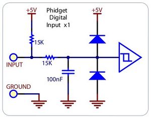
A functional block diagram from the board manual is shown below:
Because of the internal pull-up, When an input is grounded it is read as true. There is also filtering on the inputs to minimize false triggers. This circuitry allows a simple direct connection from Port 0 and Port 1 to a center-off DPDT switch that connects one or the other to ground.
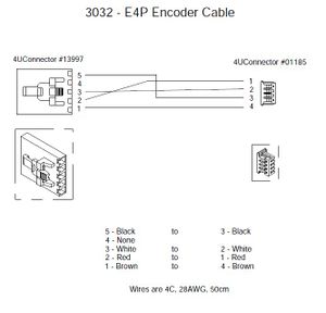
The motor encoder is connected to the card using the encoder input and a 4-position crimped connector. Phidgets also provides a cable that may be used if its length is suitable. The wiring of the required connector is shown below. In our system a Phoenix 8-contact plug and socket provides a simple disconnect of the focuser motor from the electronics.
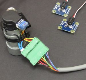
The motor with the Phoenix connector is shown below. Phoenix pin 1 in our numbering is upper right, connected to the encoders. Pin 8 on the lower left goes to the motor power.
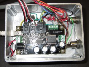
The cable connects to the Phidgets card shown in its housing.
The completed enclosure is shown before installation on the telescope.
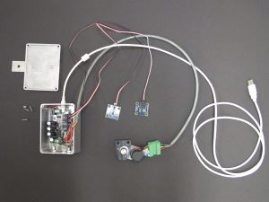
This overview shows the focuser motor with its wiring harness, two temperature sensors, and the control module.
Replacement Motors and Encoders
In the event the encoder or the motor fails, an alternative to the Celestron part is offered by Phidgets. One that appears to be suitable is their model 3264E_0, a 12 V, 8.4 Kg-cm, 28 RPM, 139:1 gearmotor and encoder with a 6 mm shaft. The encoder is the same type used on the Celestron motor, and the shaft will match the Hedrick focuser shaft extension and adapter to the bevel gear. The motor has good torque, but not so high that it will damage its own gears if it stalls. Its stall current is 1.5 A, within the capacity of the Phidgets controller.
The encoders on the Celestron motors are interchangable. Under the plastic cover the encoder disk is held to the shaft by a set screw. If the screw is carefully loosened, the disk may be slipped off. Two screws hold the circuit board which may be removed and swapped for a replacement. We note this because we had an encoder circuit board failure on CDK20N after 6 years of service.
Focuser Software
PyFocus is a Python-based set of programs to control the focuser. It is all-in-one standalone code that is scriptable, and also configured to work with XmTel and XmCCD for telescope control and image acquisition. Although the code is designed to enable setting the focus based on the measured image defocus for a Planewave CDK20, these parameters are easily modified. It may also be adapted to controlling any small encoded DC motor using the Phidgets hardware.
